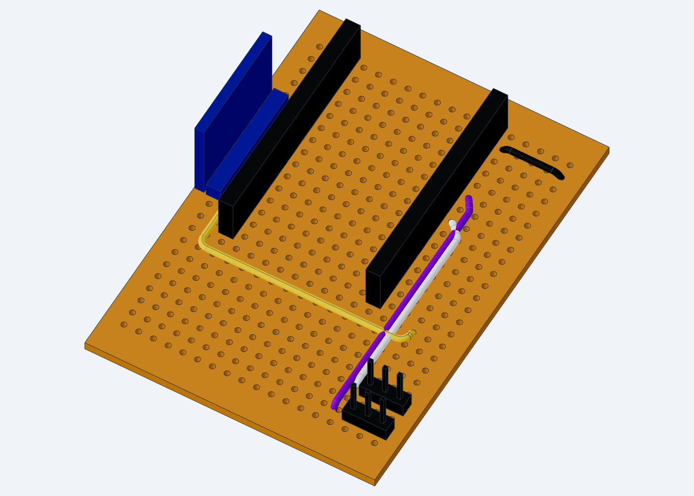
The electronics are built in a fixed order: the perfboard
first, on the bench, then the pump, the battery and the power parts
inside the deck, the relay, and finally the board, the sensors and the
servos. Each step shows the parts it adds in colour over a ghosted deck.
Every wire has an ID (J for board jumpers, W for wires) that matches the
cut list at the end. Each step is also a 3D scene
(STEP/guide/g1_board_top.step …
g7_servos.step) that can be rotated and zoomed in the
viewer: run scripts/view.sh wiring to start it and print
the links; each render below opens its scene when clicked.
Names — the glossary shows every module and electrical term named below.
Colour code — every image and the cut list use the same colours.
| Colour | Net |
|---|---|
| red | battery +7.4 V (after the BMS and the switch) |
| orange | +5 V from the buck |
| yellow | +3.3 V from the ESP32 |
| black | GND |
| green | flame sensor signal (AO) |
| blue | relay control (IN) |
| white, purple | servo signals on the board (J3, J4), BMS balance wire (W3) |
Board coordinates — the labels printed on the copper
side name every hole: columns 1 to 18 along the short edge, rows A to X
along the long edge. A hole is written as row and column,
e.g. Q5. With the component side up and the ESP32’s USB end
toward you, column 1 is on the left and row X is nearest to you. The
ESP32 headers sit in columns 6 and 16, rows X to J; the IMU stands in
column 18, rows S to L.
Power path — the diagram shows how energy flows, and the dashed path how the ESP32 switches the pump; the steps below build it from the battery outward.
flowchart LR
  BAT["2 × 18650<br/>(2S, 6.0–8.4 V)"] --> BMS["BMS 2S<br/>B−/P− in the negative"]
  BMS -->|P+| SW["Rocker switch"]
  SW -->|"+7.4 V"| BUCK["XL4015<br/>set to 5.0 V"]
  SW -->|"+7.4 V"| COM["Relay COM"]
  COM -->|"NO, while IN is at GND"| PUMP["Pump R385<br/>+ 1N4007"]
  BUCK -->|"+5 V"| BOARD["Perfboard rails"]
  BOARD --> ESP["ESP32 VIN"]
  BOARD --> SERVOS["Pan and tilt servos"]
  BOARD --> RELAY["Relay VCC"]
  ESP -->|"3V3"| SENS["6 flame sensors"]
  ESP -.->|"D26 high"| DRV["2N2222A<br/>relay driver"]
  DRV -.->|"pulls to GND"| RIN["Relay IN"]
  RIN -.->|"closes COM–NO"| COM
Soldering habits — tin each wire end before it goes into a hole, keep wires flat against the board, and slide heat-shrink over every wire-to-tab or wire-to-wire joint before soldering it. After each step, check the new connections with the multimeter’s continuity mode before moving on.
The board is built completely on the bench, with no part of the deck involved.
The hole map below is the exact reference for every hole on the component side.
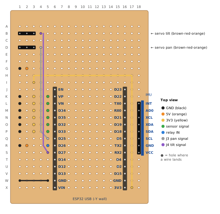
D1–D3 (pan servo) and one into
B1–B3 (tilt servo), long pins up.S18 (VCC) to L18 (INT), the module facing
the board edge, and solder the 8 legs from below. Keep it square to the
board: it is the turret’s level reference.The bottom side carries three bare-wire rails, the IMU’s two supply wires and short solder bridges. The map is drawn as seen with the board flipped over, USB end away from you, so its labels read like the ones printed on the copper side.
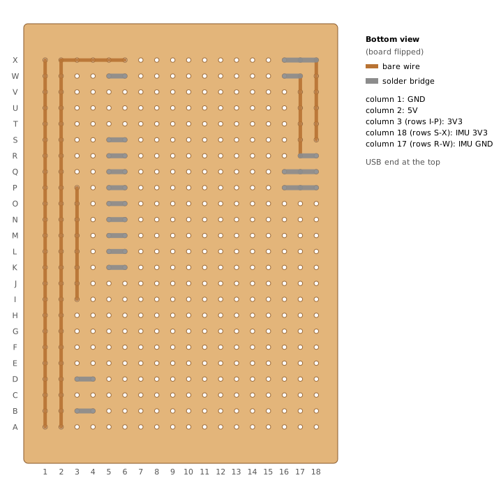
5–6 on row W and on every row from S to K;
16–17 on rows X and W; 17–18 on rows X and R;
16–17–18 on rows Q (SCL to D5) and P (SDA to D18);
3–4 on rows D and B. Heat both pads and feed solder until
it flows across.The four jumpers lie flat on the component side. Strip 3 mm at each end, push the ends through their holes and solder them on the bottom.
| Jumper | Colour | From | To | Path |
|---|---|---|---|---|
| J1 | black | W5 (ESP32 GND) |
W1 (GND rail) |
straight across row W |
| J2 | yellow | X17 (ESP32 3V3) |
I3 (3V3 rail) |
up column 17 to row H, across row H, down column 3 |
| J3 | white | D4 (pan servo signal) |
Q5 (D25) |
down column 4 |
| J4 | purple | B4 (tilt servo signal) |
S5 (D27) |
down column 4, next to J3 |
With the ESP32 still unplugged, check with the multimeter:
W6, W16).X6).X16).Q6 (D25), tilt to S6 (D27).X16 (3V3), GND to W16, SCL to Q16
(D5), SDA to P16 (D18).The wires that leave the board are soldered to the board now and connected to their parts later. Cut each one to the length in the cut list.
G2 and W11 (black, 22 AWG)
into G1. Their free ends go to the buck.| Wire | Colour | Hole | Plugs onto |
|---|---|---|---|
| W12 | orange | R2 |
relay VCC |
| W13 | black | R1 |
relay GND |
| W14 | blue | R5 |
relay IN, through the relay driver |
| W15, W16, W17 | green, black, yellow | M5, M1, M3 |
30° sensor AO, GND, VCC |
| W18, W19, W20 | green, black, yellow | P5, P1, P3 |
90° sensor AO, GND, VCC |
| W21, W22, W23 | green, black, yellow | N5, N1, N3 |
150° sensor AO, GND, VCC |
| W24, W25, W26 | green, black, yellow | K5, K1, K3 |
210° sensor AO, GND, VCC |
| W27, W28, W29 | green, black, yellow | O5, O1, O3 |
270° sensor AO, GND, VCC |
| W30, W31, W32 | green, black, yellow | L5, L1, L3 |
330° sensor AO, GND, VCC |
Dupont packs come in mixed colours; when the exact colour is missing, mark the wire with a strip of tape in the right colour near the plug.
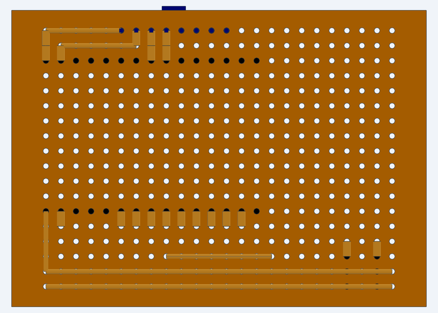
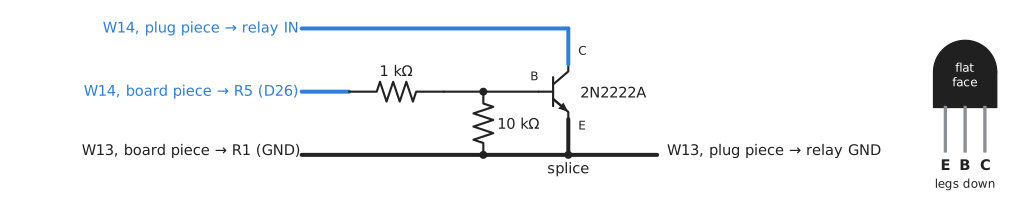
The relay module switches on when its IN pin is pulled to GND and off only when IN sits at its own 5 V, which a 3.3 V ESP32 pin cannot hold: wired straight to D26, the pin’s protection diode clamps IN near 3.8 V and the relay never releases. A 2N2222A transistor pulls IN to GND while D26 is high, so the pin never meets the module’s 5 V. It is built in the air on W14 and W13, 3 cm from their plugs, and hangs beside the relay’s pins.
The figure shows where each leg and wire piece goes, and how to tell the transistor’s legs apart.
R1;
W14’s plug does not beep to R5; in diode mode, red probe on
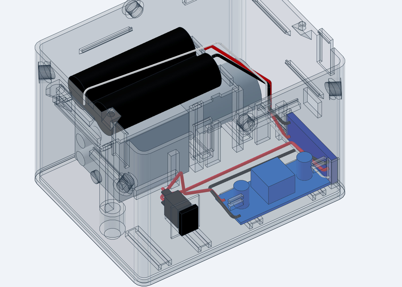
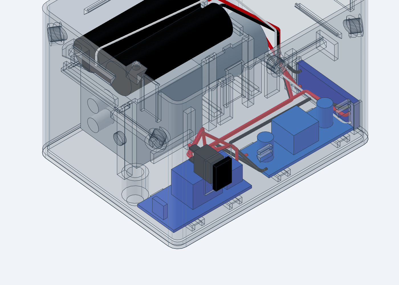
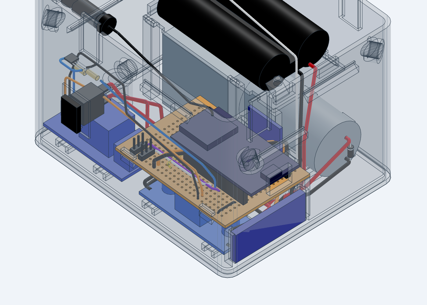
W14’s plug and black on R1 reads OL.The pump lies on the floor of the +Y half with the battery tray above it; relay and buck lie on the floor of the −Y half and the perfboard snaps in above them. Install the parts in this order: the board covers the buck and the BMS, and the tray covers the pump.
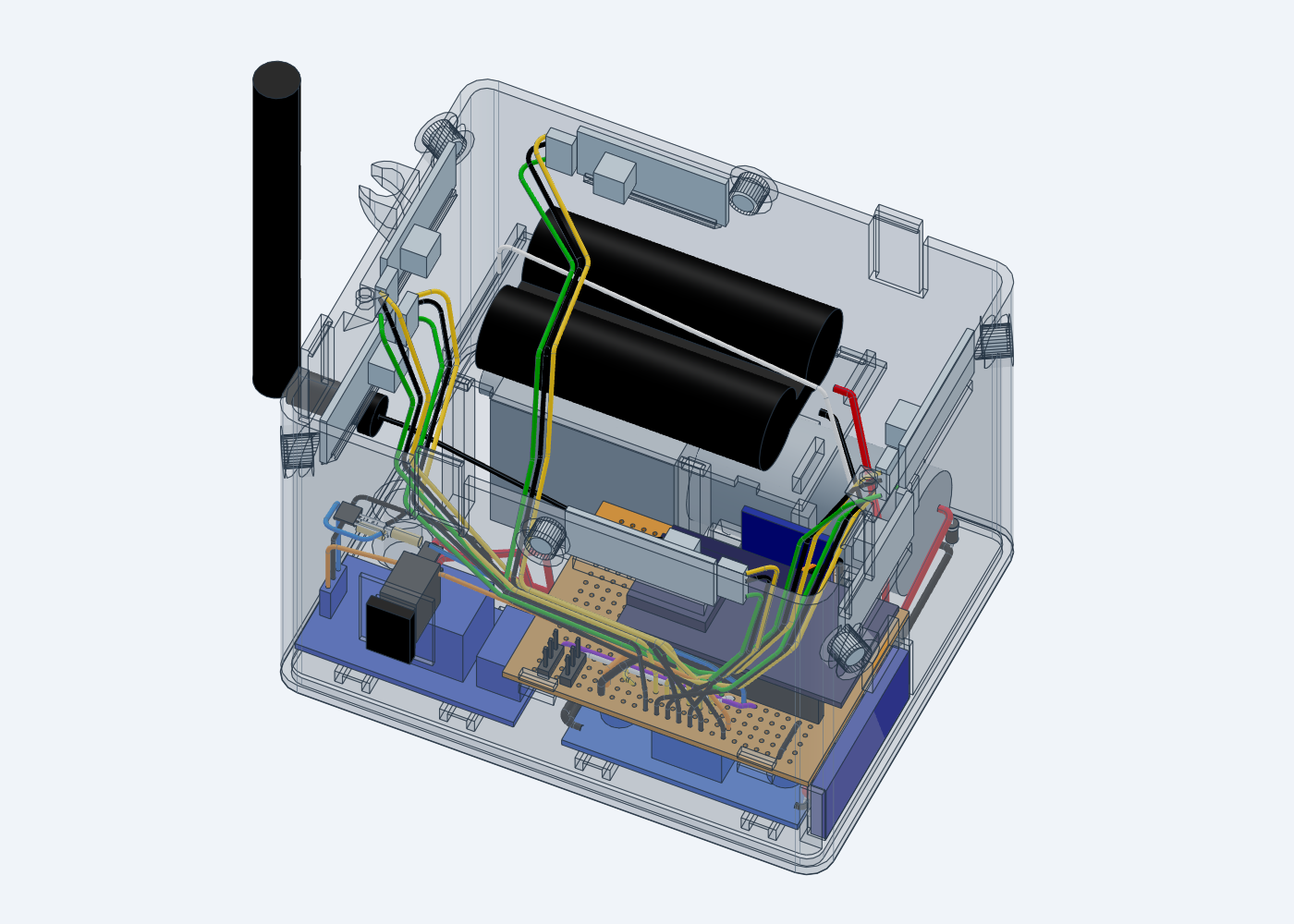
The six sensors sit at 60° steps, counted counter-clockwise from the +X wall seen from above. On the ±X walls, the sensor in the +Y half is in the top row and the one in the −Y half is in the lower row.
| Sensor | Wall | Row | Header end toward | Wires |
|---|---|---|---|---|
| 30° | +X | top | −Y | W15–W17 |
| 90° | +Y | top | −X | W18–W20 |
| 150° | −X | top | −Y | W21–W23 |
| 210° | −X | lower | +Y | W24–W26 |
| 270° | −Y | top | +X | W27–W29 |
| 330° | +X | lower | +Y | W30–W32 |
Install the lower-row sensors (210°, 330°) before the top-row sensors on the same wall. The 90° sensor’s wires cross above the battery cells to the −X side; lift them aside to change the cells.
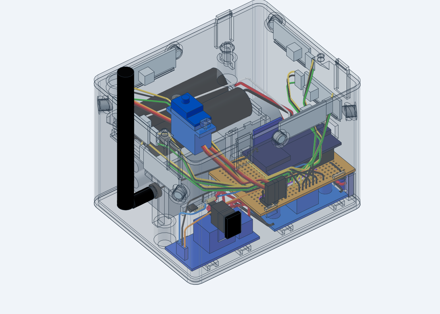
The ESP32 connects to USB only out of the board: its USB 5 V reaches VIN and the 5V rail, so on the board it would back-feed the buck’s output and run the relay and the servos from the computer’s port, whether the switch is on or off. On the board, the turret is controlled over WiFi through the routes below; each one answers with the status.
| Route | Does |
|---|---|
/status |
reports pump, aim, sensor levels, IMU and calibration |
/calibrate |
stores the sensors’ ambient level |
/level |
stores the current orientation as level |
/auto?on=0 |
stops automatic mode (on=1 restarts it) |
/aim?pan=0&tilt=0 |
aims the head, in degrees; only with automatic mode off |
/pump?on=1 |
starts the pump (on=0 stops it) |
/status at the WiFi address./auto?on=0, then
/pump?on=1 and /pump?on=0: the relay clicks
both times and the pump runs between them./calibrate. Until then, and after every restart, the turret
does not detect fire./level: the
IMU stores this orientation as level. Without it, the firmware takes the
orientation at power-up as level./status: lean[1] must turn positive. If it
turns negative, negate IMU_DECK_Y in
firmware/include/config.h, reload the firmware and repeat
the level step.Lengths come from the routed harness in the model and include stripping allowance. Cut wires 1 cm longer when in doubt; trim on assembly.
| Wire | Colour | Gauge | From | To | Cut length |
|---|---|---|---|---|---|
| J1 | black | 30 AWG | ESP32 GND (W5) | GND rail (W1) | 3.5 cm |
| J2 | yellow | 30 AWG | ESP32 3V3 (X17) | 3V3 rail (I3) | 10.0 cm |
| J3 | white | 30 AWG | pan header SIG (D4) | D25 (Q5) | 5.5 cm |
| J4 | purple | 30 AWG | tilt header SIG (B4) | D27 (S5) | 6.5 cm |
| W1 | red | 22 AWG | battery holder + | BMS B+ | 11.0 cm |
| W2 | black | 22 AWG | battery holder - | BMS B- | 9.5 cm |
| W3 | white | 30 AWG | battery holder centre strap | BMS BM | 22.5 cm |
| W4 | black | 22 AWG | BMS P- | buck IN- | 14.0 cm |
| W5 | red | 22 AWG | BMS P+ | switch terminal 1 | 16.5 cm |
| W6 | red | 22 AWG | switch terminal 2 | buck IN+ | 10.0 cm |
| W7 | red | 22 AWG | switch terminal 2 | relay COM | 8.0 cm |
| W8 | red | 22 AWG | relay NO | pump + | 15.5 cm |
| W9 | black | 22 AWG | buck IN- | pump - | 16.0 cm |
| W10 | orange | 22 AWG | buck OUT+ | board 5V (G2) | 15.0 cm |
| W11 | black | 22 AWG | buck OUT- | board GND (G1) | 17.0 cm |
| W12 | orange | Dupont | relay VCC | board 5V (R2) | 14.5 cm |
| W13 | black | Dupont | relay GND | board GND (R1), spliced to the relay driver’s emitter | 16.0 cm |
| W14 | blue | Dupont | relay IN | board D26 (R5), through the relay driver | 17.5 cm |
| W15 | green | Dupont | sensor 30° AO | board M5 | 10.5 cm |
| W16 | black | Dupont | sensor 30° GND | board M1 | 11.0 cm |
| W17 | yellow | Dupont | sensor 30° VCC | board M3 | 11.0 cm |
| W18 | green | Dupont | sensor 90° AO | board P5 | 19.0 cm |
| W19 | black | Dupont | sensor 90° GND | board P1 | 19.0 cm |
| W20 | yellow | Dupont | sensor 90° VCC | board P3 | 19.0 cm |
| W21 | green | Dupont | sensor 150° AO | board N5 | 15.0 cm |
| W22 | black | Dupont | sensor 150° GND | board N1 | 15.5 cm |
| W23 | yellow | Dupont | sensor 150° VCC | board N3 | 15.5 cm |
| W24 | green | Dupont | sensor 210° AO | board K5 | 15.5 cm |
| W25 | black | Dupont | sensor 210° GND | board K1 | 15.5 cm |
| W26 | yellow | Dupont | sensor 210° VCC | board K3 | 16.0 cm |
| W27 | green | Dupont | sensor 270° AO | board O5 | 9.0 cm |
| W28 | black | Dupont | sensor 270° GND | board O1 | 9.5 cm |
| W29 | yellow | Dupont | sensor 270° VCC | board O3 | 10.0 cm |
| W30 | green | Dupont | sensor 330° AO | board L5 | 12.0 cm |
| W31 | black | Dupont | sensor 330° GND | board L1 | 12.0 cm |
| W32 | yellow | Dupont | sensor 330° VCC | board L3 | 12.5 cm |
The pieces on the board’s solder side (rails and bridges). Bare wire is 22 AWG with all its insulation pulled off, or a straightened resistor lead; the lengths include 5 mm at each end to hold it while soldering, trimmed afterwards. The IMU ground length includes 8 mm of stripping at each end.
| Piece | Wire | From | To | Cut length |
|---|---|---|---|---|
| GND rail | bare 22 AWG | X1 | A1 | 7.0 cm |
| 5V rail | bare 22 AWG | X2 | A2 | 7.0 cm |
| 3V3 rail | bare 22 AWG | P3 | I3 | 3.0 cm |
| VIN to 5V | bare 22 AWG | X2 | X6 | 2.5 cm |
| IMU 3V3 | bare 22 AWG | X18 | S18 | 2.5 cm |
| IMU GND | insulated 30 AWG | W17 | R17 | 3.0 cm |
firmware/include/config.h uses the same pins.
| ESP32 pin | Connected to |
|---|---|
| D34 | 30° flame sensor AO |
| D33 | 90° flame sensor AO |
| D35 | 150° flame sensor AO |
| VP (GPIO36) | 210° flame sensor AO |
| D32 | 270° flame sensor AO |
| VN (GPIO39) | 330° flame sensor AO |
| D25 | pan servo signal |
| D27 | tilt servo signal |
| D26 | relay IN, through the 2N2222A driver |
| VIN | 5V rail |
| 3V3 | 3V3 rail (sensor supply) |
| GND | GND rail |