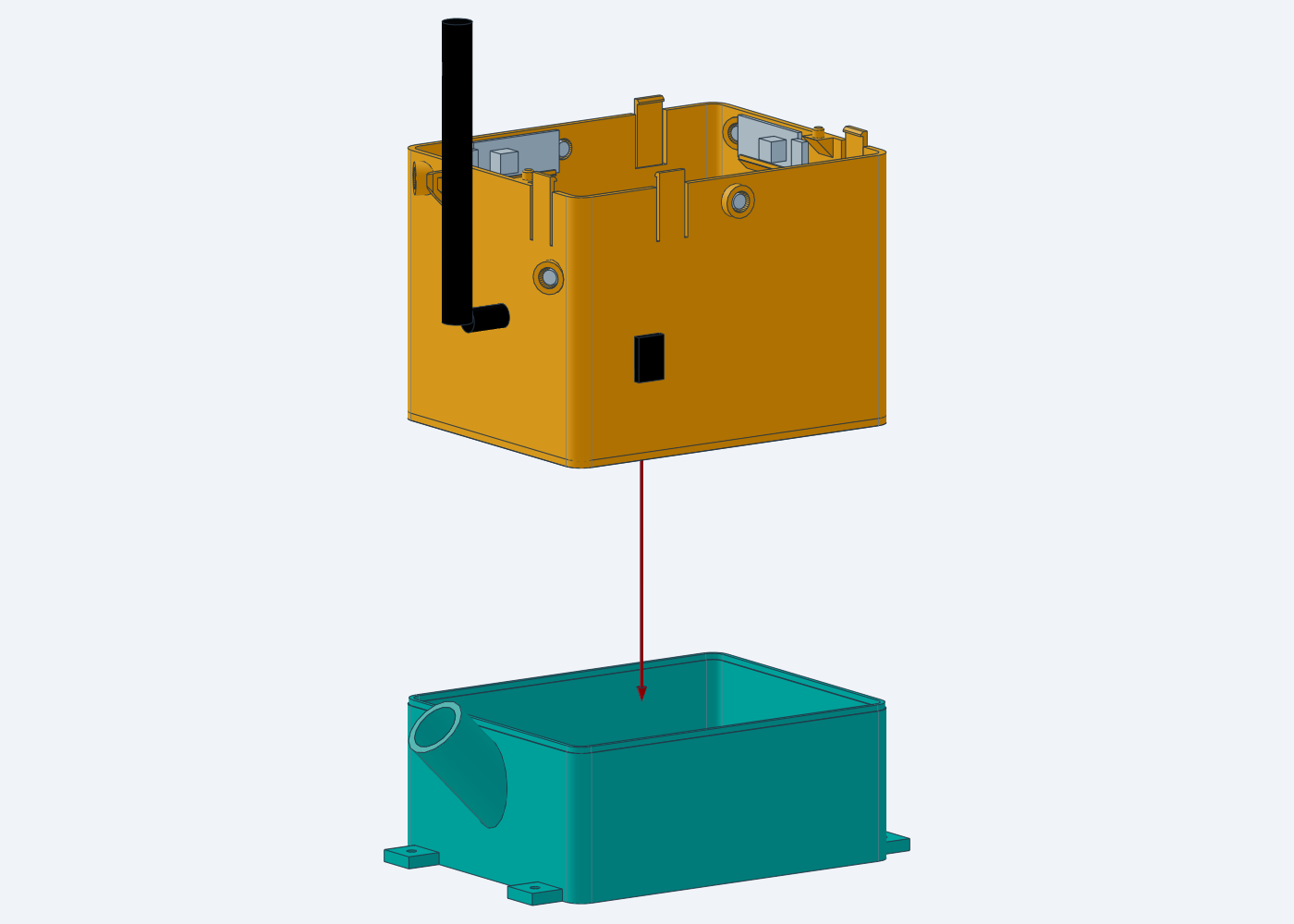
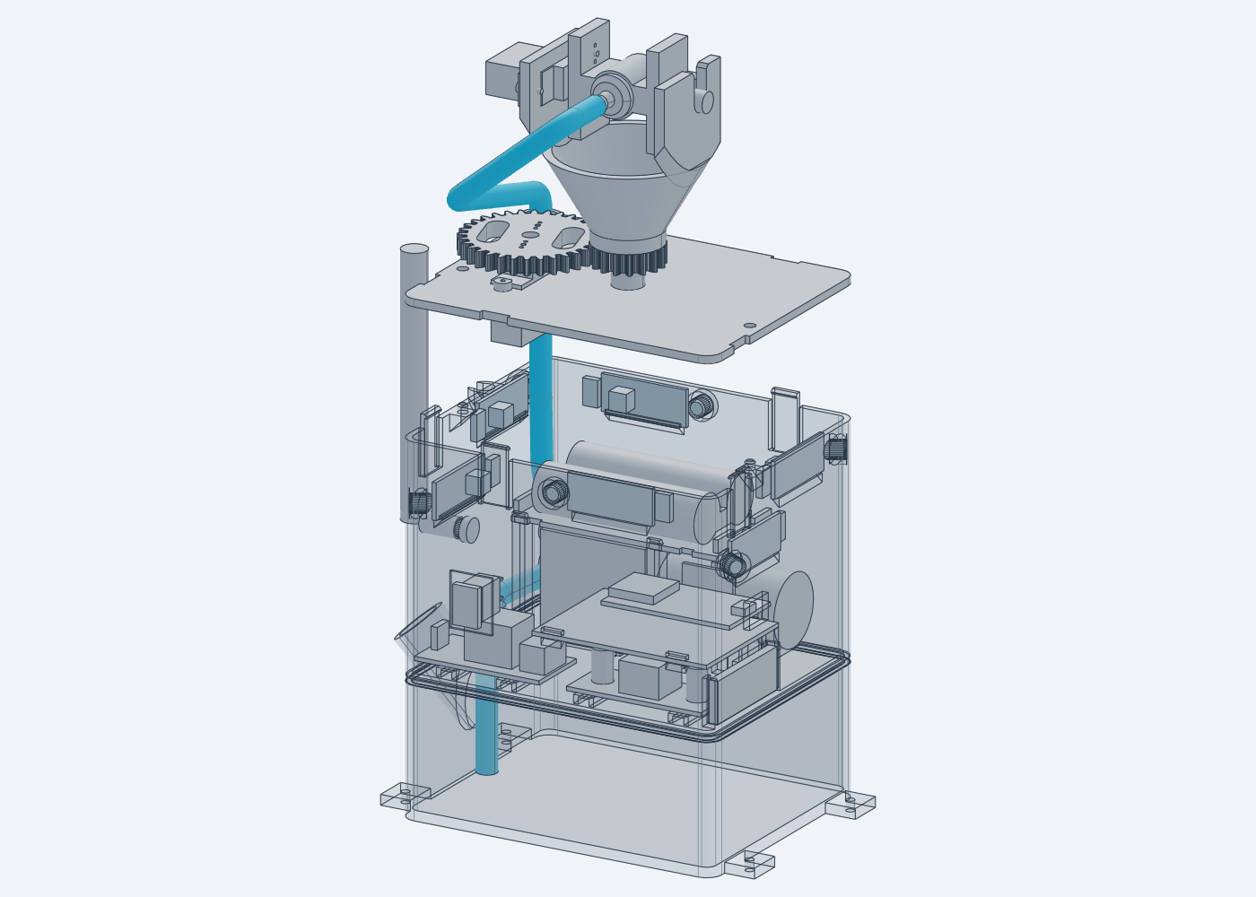
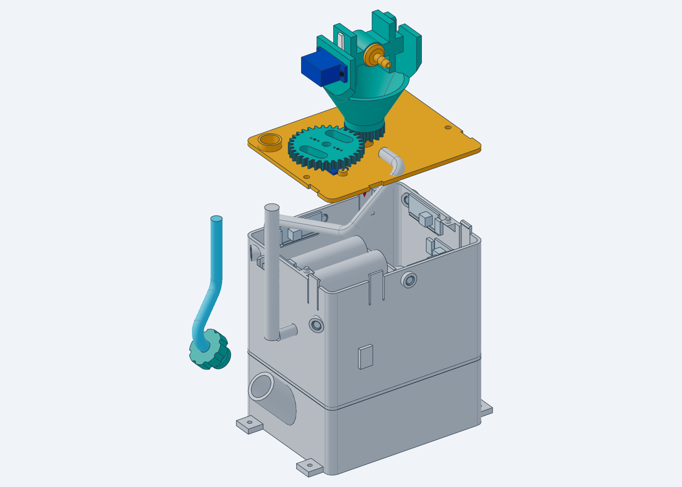
The head is built first, on the cover, on the bench; then
the housing closes around the wired deck. Each step shows its parts in
colour, pulled out along the direction they go in, with a red arrow to
where they end up; parts from earlier steps are grey. Each step lists
the parts it takes. Every step is also a 3D scene
(STEP/guide/m01_bearing.step … m11_cover.step)
that can be rotated and zoomed in the viewer: run
scripts/view.sh to start it and print every link; each
render below opens its scene when clicked.
Before starting
Names — the glossary
shows every part and feature named below.
Electronics — the deck is wired through the
flame-sensor step of the wiring guide and the
firmware is loaded (the first three items of its first power-up). The servo steps
below centre a servo by plugging it onto its header on the board (pan on
row D, tilt on row B, brown on column 1), switching on and opening
/auto?on=0, then /aim?pan=0 or
/aim?tilt=0 at the turret’s WiFi address; switch off and
unplug it before going on.
Directions — +Y is the side of the cover with the
hose hole (the pump side); the pan servo sits on the −X side of the
cover. The nozzle points toward +Y at pan 0.
Joints — apart from the servos, nothing is screwed:
parts snap, press or slide into place. Snaps are designed for one firm
push; when one does not go, check the part’s orientation before pushing
harder.
Screws — the servo ear screws and the horn centre
screw come in each servo’s bag; the 2 × 6 mm horn screws are bought
separately, and the horn’s middle holes may need a 2 mm drill for them
to pass.
Head
Bearing
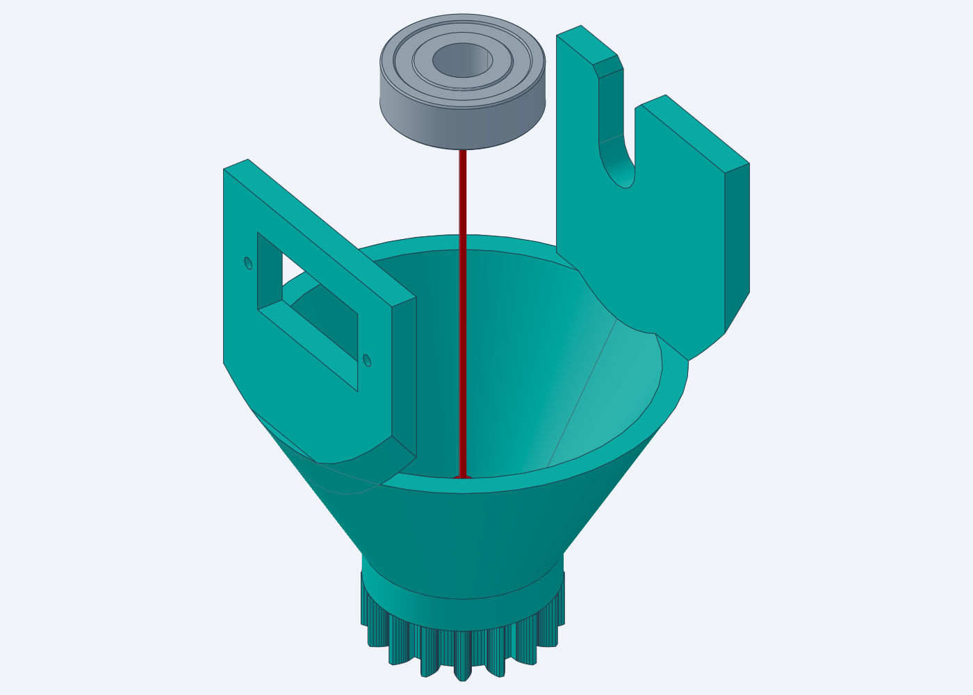
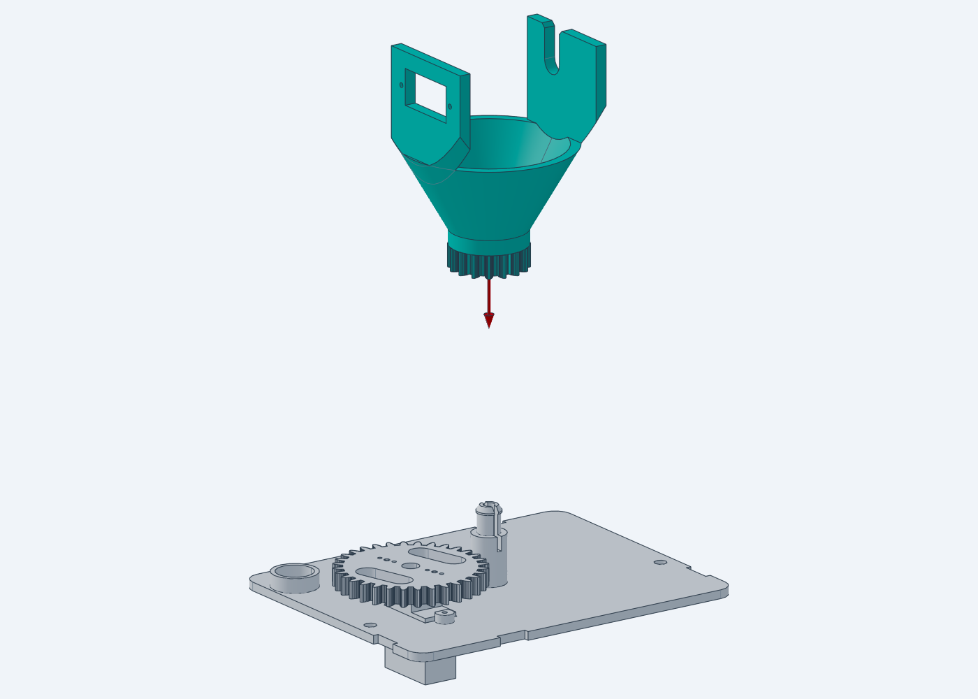
Parts: turntable, 608ZZ bearing.
Set the turntable on its gear. Press the bearing into the hub from
above, inside the bowl, until it rests on the ledge. Push on the outer
race only, with a socket or a flat block, so it goes in square: it drops
in by hand for the first millimetre, then the six ribs inside the hub
take a firm push.
Pan servo
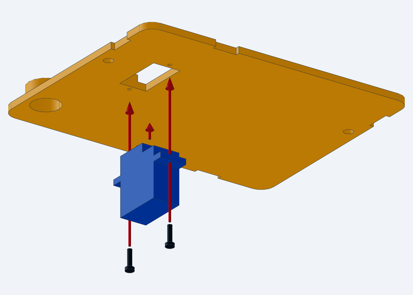
Parts: cover, pan servo, 2 servo screws.
Turn the cover over. Push the servo into its pocket from below,
shaft first, body toward −Y, until the ears rest on the bosses.
Drive the two screws through the ears into the bosses.
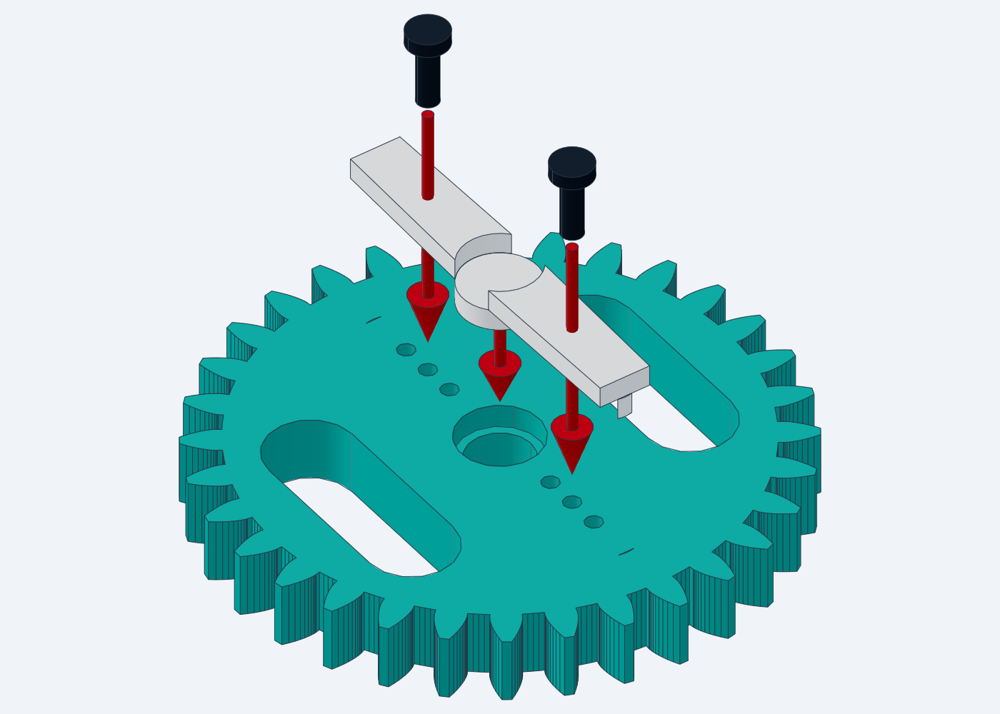
Lay the gear with its horn pocket facing up and press the double-arm
horn into the pocket, spline socket facing up.
Drive the two horn screws through the horn’s middle holes (10 mm
from the hub) into the gear.
Pan gear
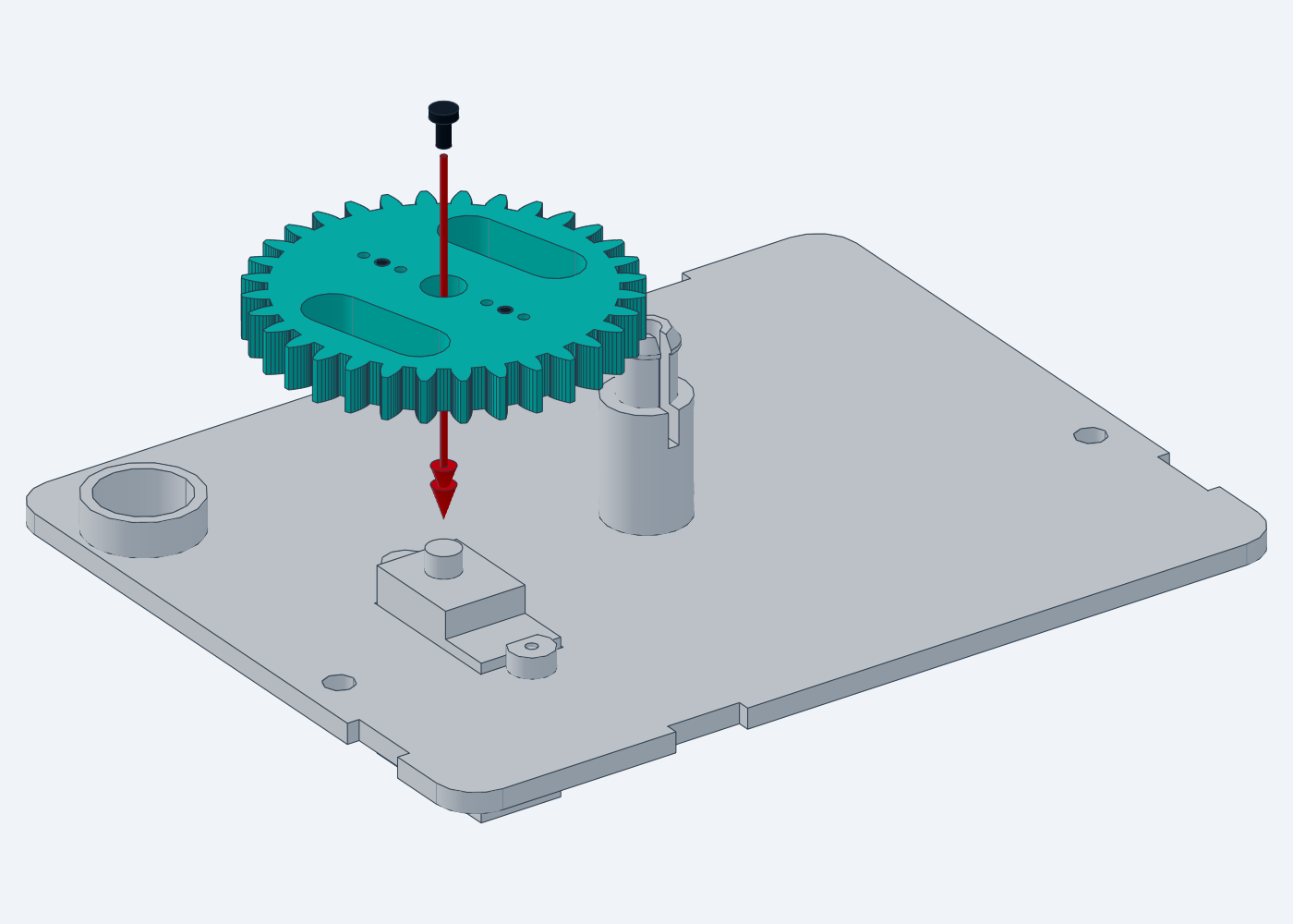
Parts: gear and horn from the previous step, horn centre screw.
Centre the pan servo (/aim?pan=0).
Push the gear onto the servo spline, horn side down, and drive the
centre screw through the hole in the middle of the gear. This comes
before the turntable: its bowl covers the gear’s centre.
Turntable
Parts: turntable with its bearing.
With the pan servo still centred, hold the turntable with its
uprights along X, the upright with the rectangular window on the −X
side.
Lower it onto the cover’s pin, its gear meshing with the servo gear,
and press down on the hub until the pin’s split head clicks above the
bearing. The turntable turns freely by hand and has no vertical
play.
Switch on and open /auto?on=0, then
/aim?pan=-180 and /aim?pan=180: the turntable
turns half a turn each way without binding.
To take the turntable off again, squeeze the two halves of the pin’s
head together with pliers, from above, and lift.
Nozzle and horn
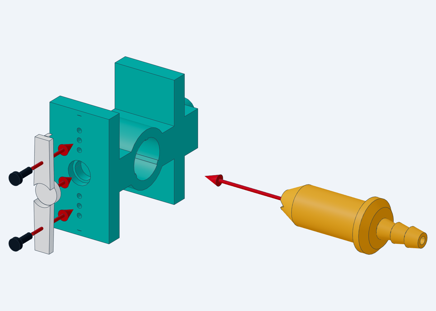
Parts: tilt arm, fan nozzle, double-arm horn, 2 × 2 × 6 mm
self-tapping screws.
Push the fan nozzle into the arm’s ring from the back, tip first,
until its flange stops against the ring; the three ribs inside the ring
hold it. Turn it so the groove across its tip runs across the arm, from
one side plate to the other: the fan spreads in the groove’s plane, so
it is horizontal when the nozzle is level.
Press the horn into the pocket on the left plate’s outer face (the
plate without the round stub), spline socket facing out, and drive the
two horn screws through its middle holes into the plate.
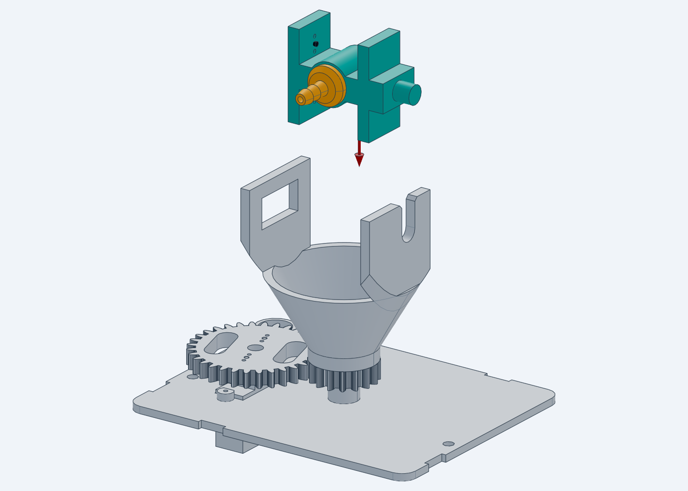
Tilt arm
Parts: tilt arm from the previous step.
Hold the arm between the uprights, nozzle toward +Y and level, horn
toward the window.
Lower it until its stub sits at the bottom of the open slot in the
right upright. Keep holding it level for the next step.
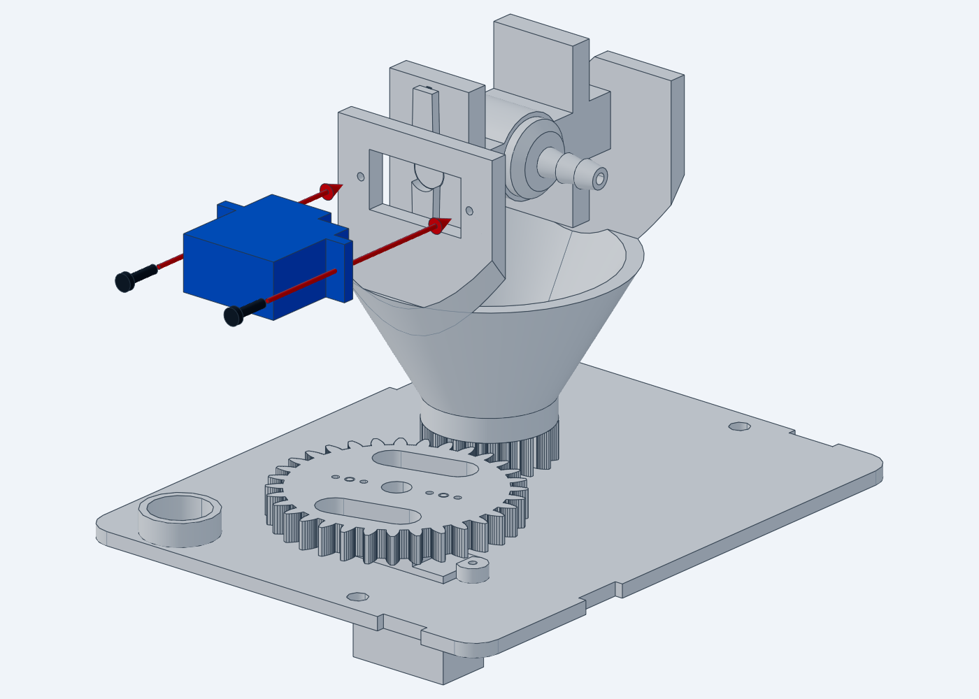
Tilt servo
Parts: tilt servo, 2 servo screws.
Centre the tilt servo (/aim?tilt=0) while it is still
loose.
Push it through the window in the left upright from outside, shaft
first, and guide its spline into the horn’s socket while the arm stays
level. Push until the ears rest on the upright.
Drive the two screws through the ears into the upright. The arm can
no longer slide sideways: the spline holds its left side, and its spacer
sits against the right upright.
Switch on and open /auto?on=0, then
/aim?tilt=-60 and /aim?tilt=60: the nozzle
swings down and up without touching the turntable.
Housing
Deck on the tank
Parts: tank, wired deck, neutral silicone.
Run a continuous bead of neutral silicone along the groove in the
bottom of the deck’s floor.
Press the deck onto the tank, the lip into the groove, with the
walls flush all around and the tank’s spout under the deck’s −X wall.
Wipe off what squeezes out.
Let the silicone cure as its tube specifies (usually 24 h) before
filling.
Hoses
Parts: 3/16” ID hose: 12 cm (suction) and 35 cm (outlet); 3 small zip
ties; neutral silicone.
Dip each hose end in hot water for a few seconds before pushing it
onto a barb; it grips as it cools.
Push the 12 cm hose onto the pump’s lower barb (the inlet; check the
marks on the pump head), bend it toward −Y and feed it down through the
collar in the deck’s floor. Its end sits just above the tank floor; trim
it if it presses on the floor. Run a bead of silicone around the hose
where it leaves the collar’s top.
Push the 35 cm hose onto the pump’s upper barb and lead it in a
loose curve into the −X/+Y corner, up toward the cover’s hole. A tight
bend kinks the hose.
Tighten a zip tie over the hose on each pump barb and trim the
tails.
Hold the cover with the head about 5 cm above the deck. Feed the
outlet hose up through the cover’s hole and push it onto the nozzle’s
barb, behind the turntable. Tighten the third zip tie over it.
Plug both servo cables onto the board as in the wiring guide’s servos step; the tilt cable goes down the
hole with the hose.
Turn the head by hand over its full range: the loop of hose and
cable above the cover is long enough at both ends of the pan and tilt
ranges. Tie the tilt cable along the hose.
Fill the tank (see Filling) and open
/auto?on=0, /pump?on=1, then
/pump?on=0: water comes out of the nozzle and the deck seam
and hose joints stay dry.
Cover
Parts: fill plug, 13 × 17 mm O-ring, 3/16” ID hose: 12 cm (breather);
neutral silicone.
Lower the cover onto the deck, its two holes over the pins on the ±X
walls, guiding the hose and the tilt cable through the hole and keeping
every wire clear of the cover’s edge.
Press the cover down at each of the four tongues until the tongue
clicks over it.
Fill the gap between the hose, the tilt cable and the rim of the
cover’s hole with silicone, all the way around.
Roll the O-ring into the groove on the fill plug’s stem; a smear of
silicone grease makes it slide.
Push one end of the 12 cm hose into the socket in the plug’s knob,
all the way to the bottom.
Push the plug’s stem into the tank’s spout until the knob meets the
spout’s end.
Bend the hose up along the −X wall and snap it into the clip under
the deck’s rim, toward +Y of the antenna. Its end stays open, a few
millimetres above the clip; trim it there.
To open the deck, pull the tongue on the +Y wall outward with a
fingernail and lift that side of the cover, then free the other three:
one on the −Y wall, one on each X wall.
Filling
The fill spout leaves the tank’s −X end at 45° and rises outside the
deck wall. Pull out the knurled plug, its breather hose still attached,
and pour water slowly with a funnel or a squeeze bottle until the water
stands about 1 cm below the spout’s mouth: the tank holds about 540 ml.
Push the plug back in until the knob meets the spout. The breather hose
lets air in while the pump draws water; a little water may rise in it
when the turret tilts.
Mounting
The tank’s four external tabs take M3 screws, for a base plate or the
Sesame quadruped that carries the turret.