The names the guides use for the turret’s parts and their
features. Each figure paints the named things in their own colour,
listed under it; grey is the rest of the part. These colours belong to
this page only: in the wiring guide and the mechanical assembly, colour marks the parts of
the current step, servos are blue, horns white and screws dark grey.
Directions and motion
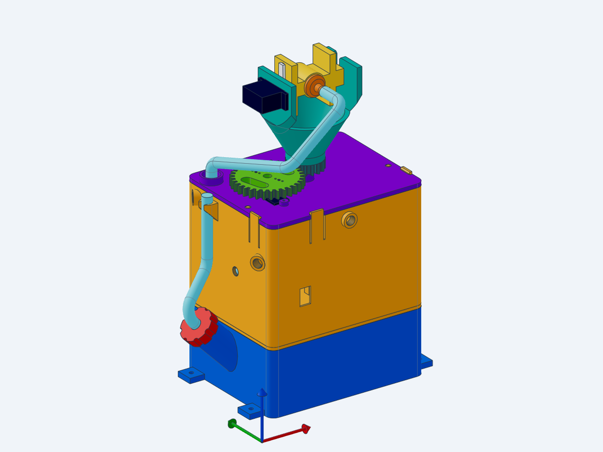
The whole turret, one colour per
part
Pan — the head turning around the vertical axis,
driven by the pan servo under the cover.
Tilt — the nozzle swinging up and down around a
horizontal axis, driven by the tilt servo on the turntable.
Axes — red arrow +X, green arrow +Y, blue arrow +Z
(up). +Y is the side with the cover’s hose hole; the nozzle points
toward +Y at pan 0.
Colours in the figure:
blue — tank
amber — deck
violet — cover
red — fill plug
pale blue — hoses
dark navy — pan servo (under the cover) and tilt servo (beside the
turntable)
green — 32T servo gear
white — horns
teal — turntable
yellow — tilt arm
orange — fan nozzle
Printed parts
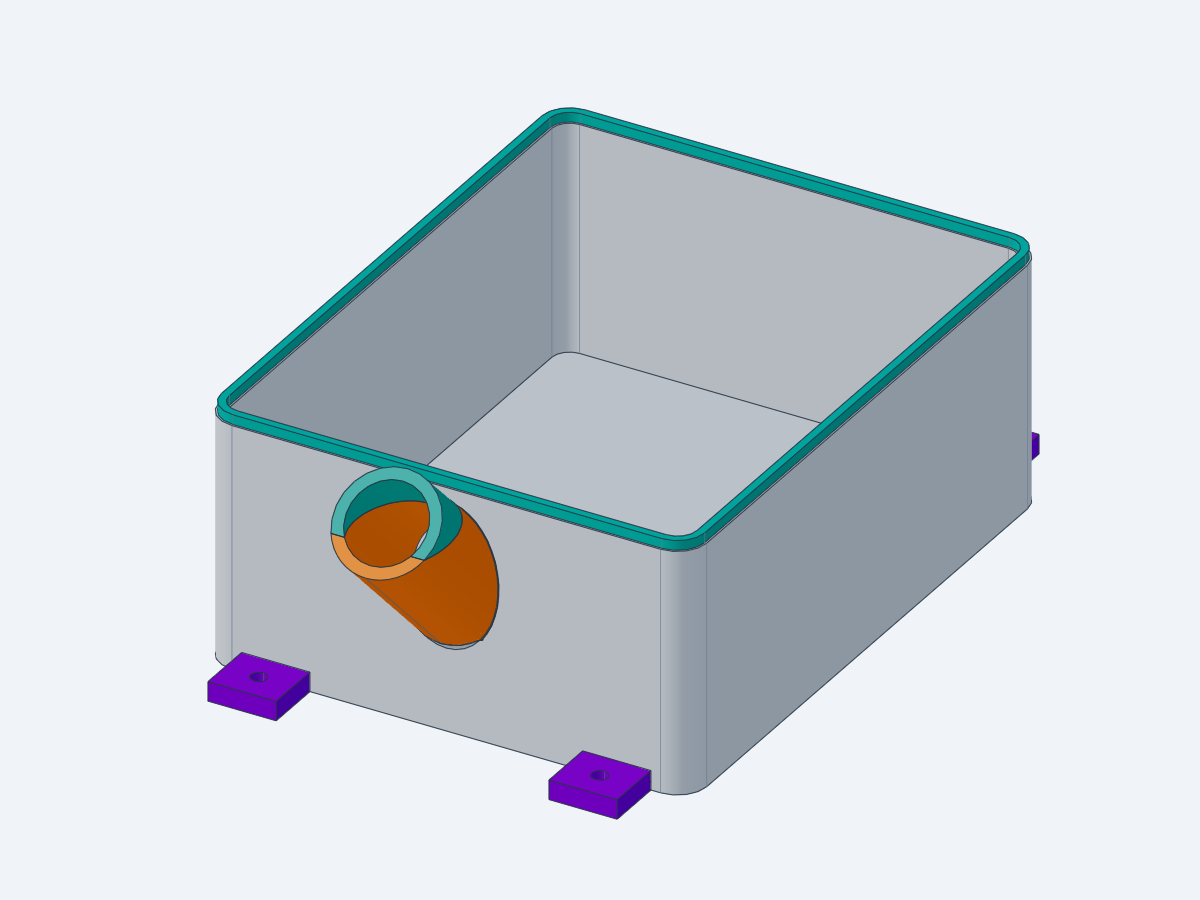
Tank
Tank
The bottom box that holds the water (about 540 ml).
teal — lip: the rim on top of the wall that enters
the groove under the deck’s floor, sealed with silicone
orange — fill spout: the 45° tube on the −X end
where water goes in; the fill plug closes it
violet — mounting tabs: four feet with M3 holes, to
screw the turret onto a base
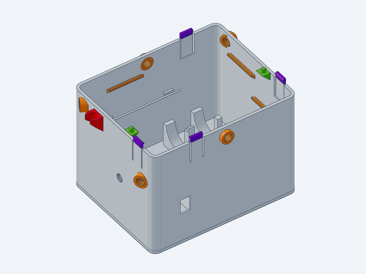
Deck
Deck
The middle box that holds the electronics; its floor is the tank’s
lid.
violet — tongues: four flexible tabs on top of the
walls that click over the cover’s edge and hold it down
orange — sensor collars: the six short tubes
through the walls, one per flame sensor, that aim each sensor and narrow
its view
teal — suction collar: the tube through the floor
that the pump’s suction hose passes down into the tank
red — breather clip: the C-shaped clip outside the
−X wall that holds the breather hose
green — cover pins: two pins on the ±X walls that
locate the cover
The groove under the floor, which takes the tank’s lip, is out of
sight in the figure.
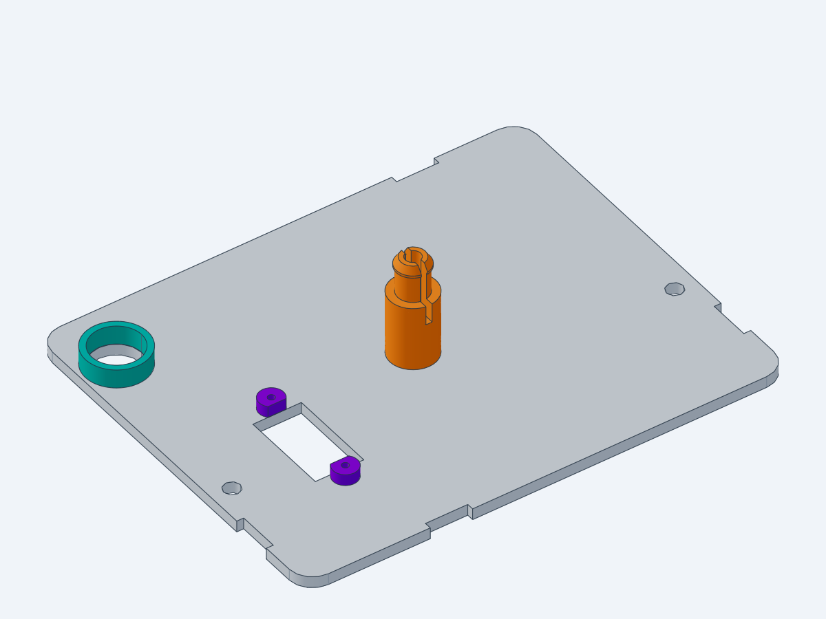
Cover
Cover
The lid on top of the deck; the whole head stands on it.
orange — pan pin: the post the turntable turns on;
its split head snaps over the bearing and holds the turntable down
violet — servo bosses: the two pads the pan servo’s
ears screw into; the servo body passes through the rectangular pocket
between them
teal — hose hole rim: the raised ring around the
hole where the hose and the tilt servo cable go up; it is sealed with
silicone
Servo gear
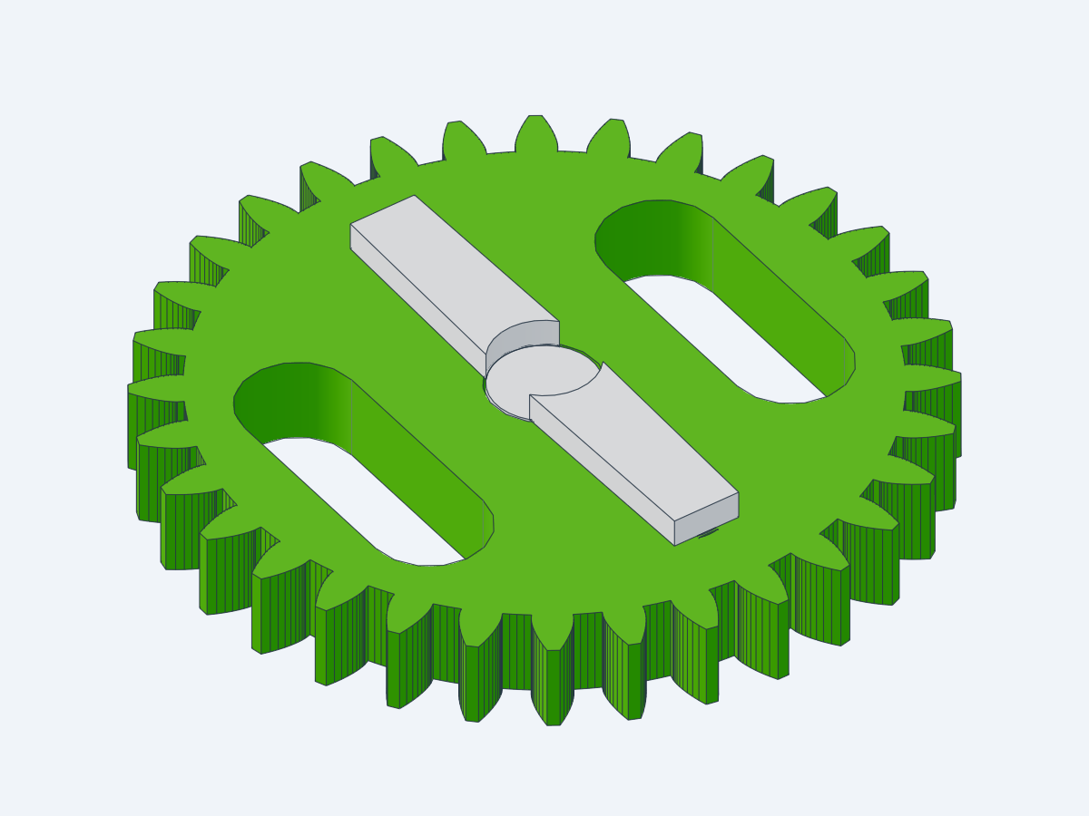
32T servo gear with a horn in its
pocket
green — 32T servo gear (32 teeth): sits on the pan
servo and drives the turntable’s 16T gear
white — horn, pressed into the gear’s horn pocket
and screwed to it (reference Servo and
horn)
Turntable
Turntable, with its bearing above the
hub
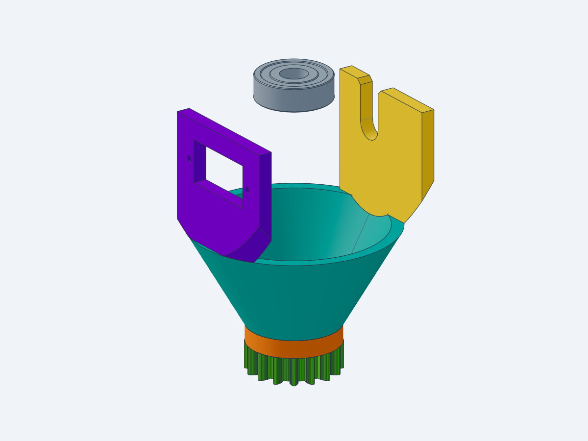
The part that pans: it turns on the cover’s pan pin and carries the
tilt arm and the tilt servo.
green — 16T gear (16 teeth): driven by the 32T
servo gear
orange — hub: the column the bearing presses into
from above; six crush ribs up its inner wall hold the
bearing, which rests on a ledge inside it
teal — bowl: the 60° cone that rises from the hub
and joins it to the uprights
violet — left upright: the wall with the
servo window, the rectangular opening the tilt servo
goes through
yellow — right upright: the wall with the
pivot slot, the open-top slot the tilt arm’s pivot stub
drops into
light grey — 608ZZ bearing: a steel ball bearing;
its outer race presses into the hub, its inner
race turns on the pan pin
Tilt arm
Tilt arm with its horn
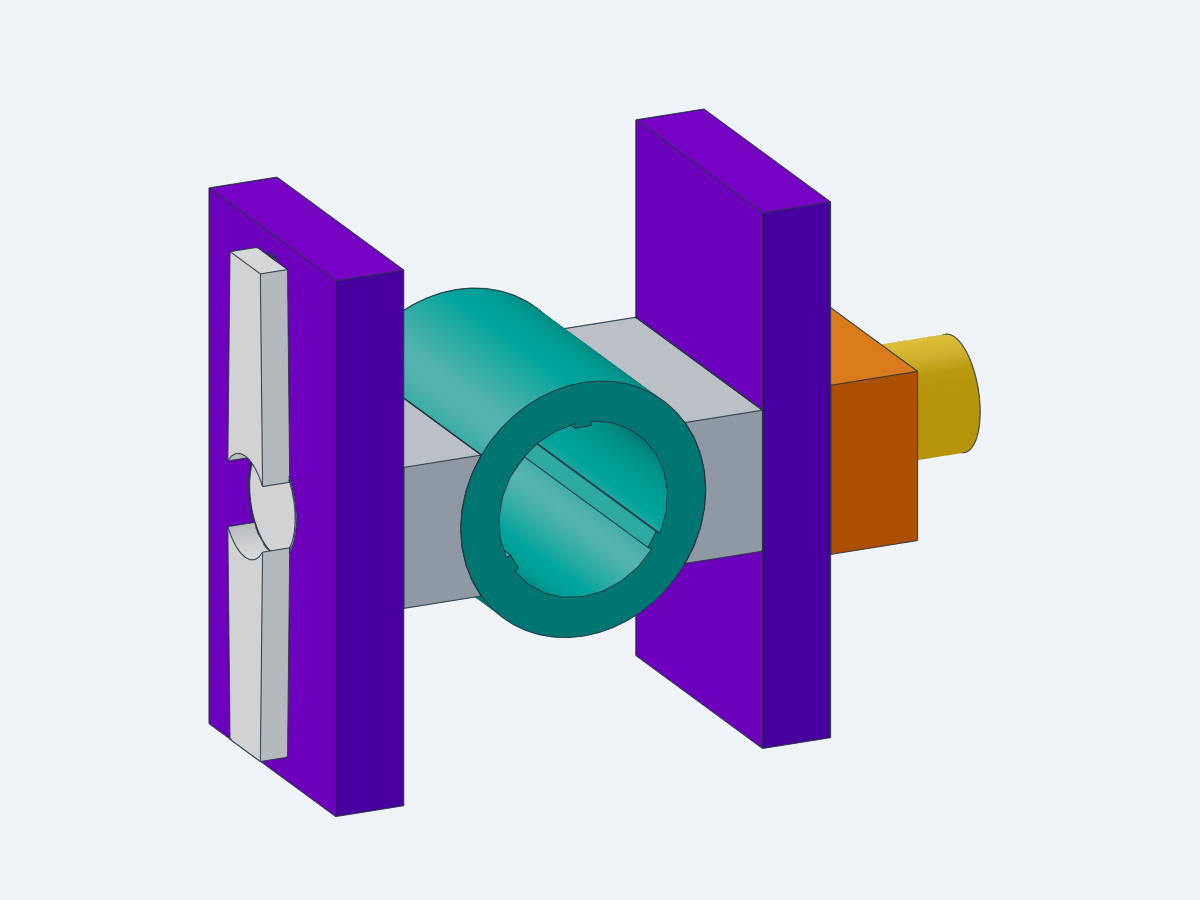
The part that holds the nozzle and tilts it, between the turntable’s
uprights.
violet — side plates: the left one carries the
horn pocket on its outer face, where the tilt servo’s
horn is screwed in
teal — clamp ring: the tube the nozzle pushes into;
the three crush ribs along its inside hold the nozzle
by a tight fit
grey — webs: the bars that join the ring to the
side plates
orange — spacer: the block between the right plate
and the right upright, so the arm cannot slide sideways
yellow — pivot stub: the round pin that turns in
the right upright’s pivot slot
white — horn
Fan nozzle
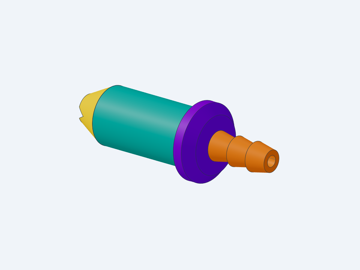
Fan nozzle
orange — hose barb: the ridged end the outlet hose
pushes onto; the ridges keep the hose from slipping off
violet — flange: the collar that stops against the
back of the clamp ring
teal — body: the part held inside the clamp
ring
yellow — tip: a V-groove across it opens a slit
that spreads the water into a flat fan
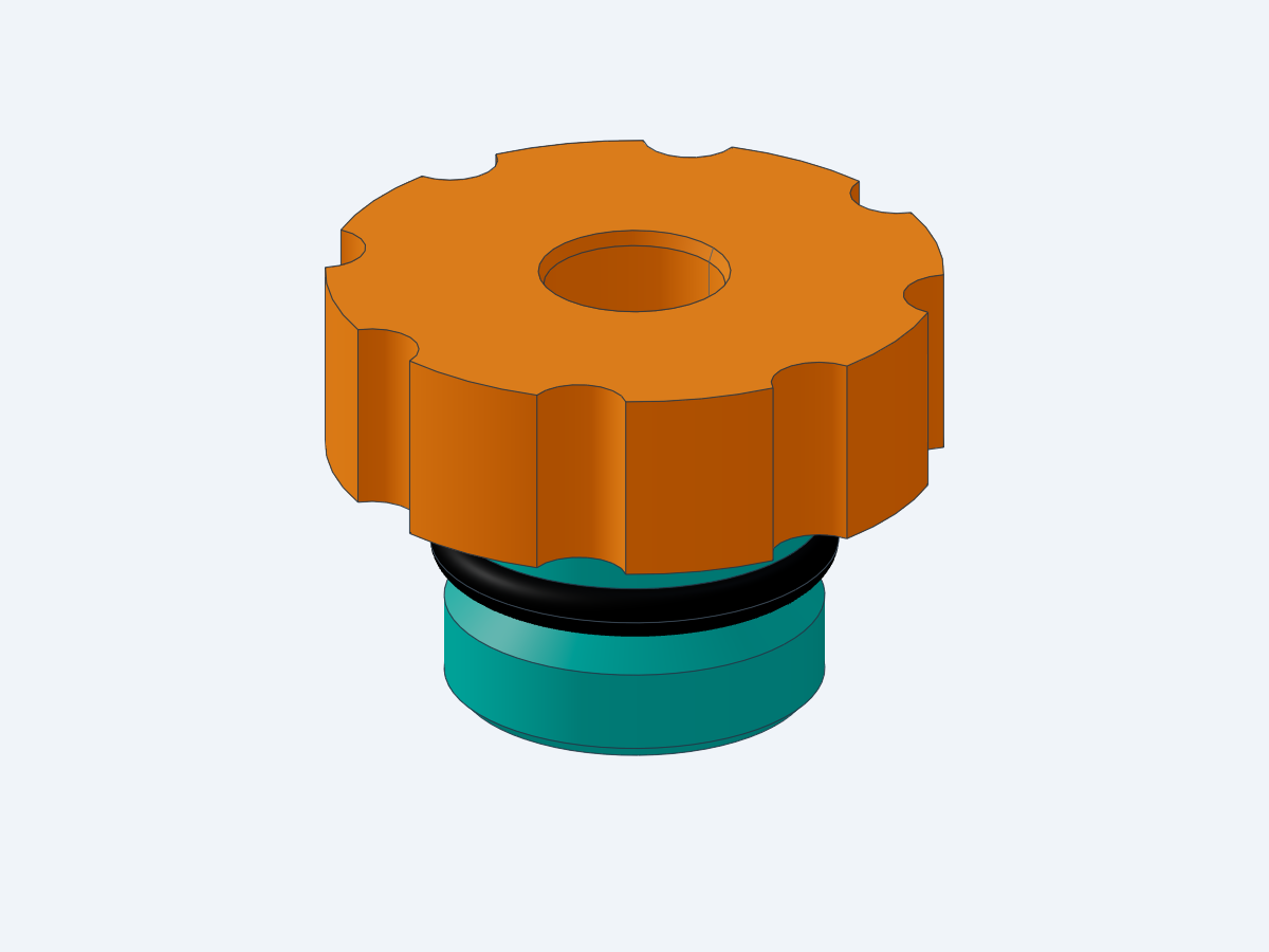
Fill plug
Fill plug, knob up, with its
O-ring
orange — knob: the ridged grip; the
breather socket in its face takes the breather hose,
which lets air into the tank while the pump draws water
teal — stem: pushes into the fill spout
black — O-ring: the rubber ring in the stem’s
groove that seals the spout
Battery tray
The plate that snaps into the deck above the pump and carries the
battery holder; teal in the electronics
figure.
Bought mechanical parts
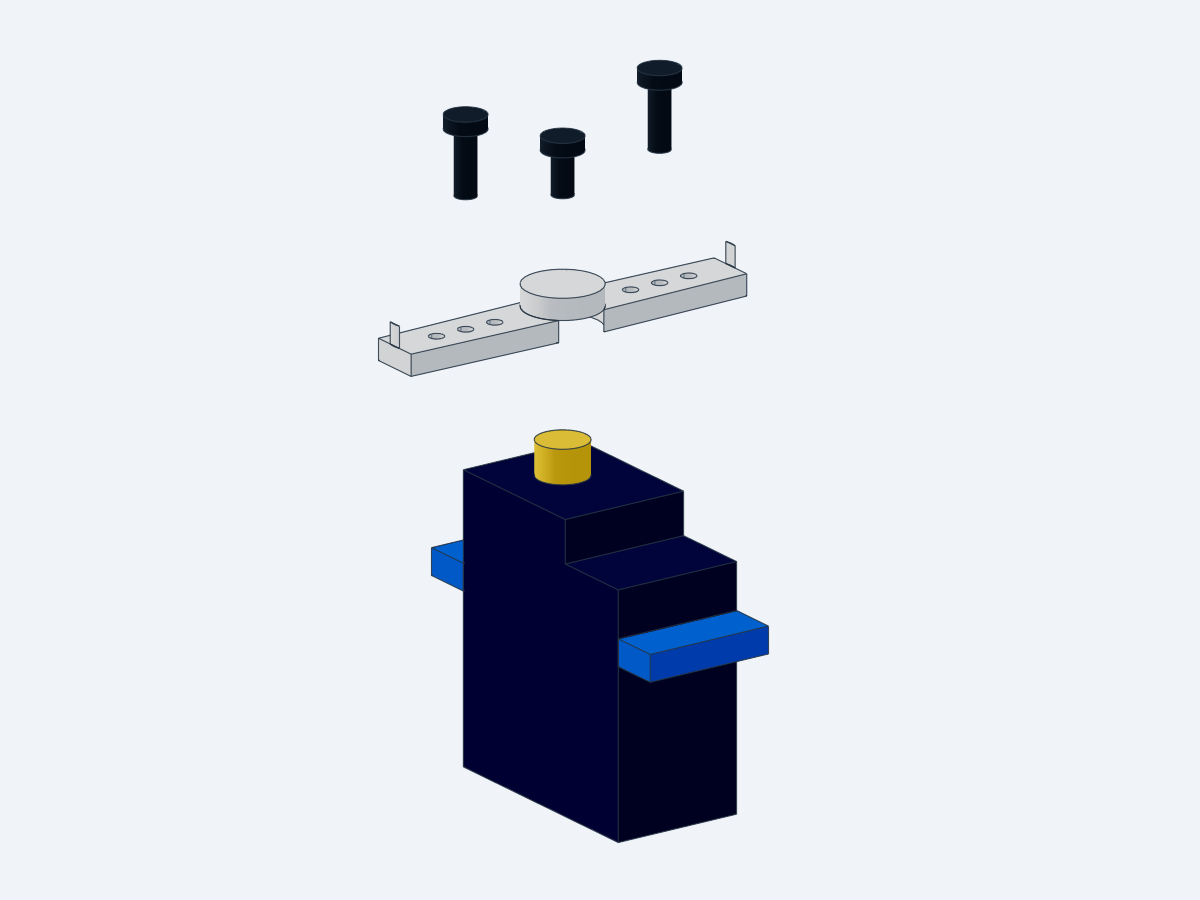
Servo and horn
MG90S servo with its horn and screws
above the shaft
The MG90S servo is a small motor that turns to an angle the ESP32
commands. The turret has two: the pan servo and the tilt servo.
dark navy — servo body
blue — ears: the flat tabs at both ends, with a
hole each for the servo ear screws
yellow — output shaft: the shaft that turns; its
fine teeth are the spline
white — horn: the plastic arm that fits on the
spline and passes the servo’s turn to a part. The turret uses the
double-arm horn (a straight bar with a hub in the
middle) from the servo’s bag. Its hub has a toothed socket that grips
the spline; the small holes along its arms take the horn
screws (2 × 6 mm self-tapping), which fix it to the 32T gear or
to the tilt arm
dark grey — horn centre screw (middle): goes
through the horn’s hub into the shaft; horn screws
(sides)
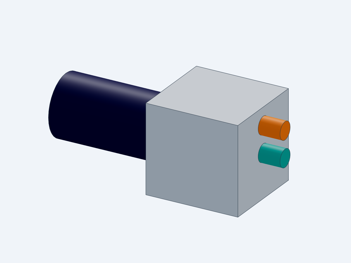
Pump
R385 pump
The R385 diaphragm pump moves the water from the tank to the
nozzle.
dark navy — motor
grey — pump head
teal — inlet barb (lower): takes the suction hose
from the tank
orange — outlet barb (upper): takes the outlet hose
to the nozzle
Small parts
Hose — 3/16” ID tube in three pieces:
suction hose (pump inlet to the tank floor),
outlet hose (pump outlet to the nozzle),
breather hose (fill plug to the breather clip).
Barb — a ridged spigot that a hose pushes onto: two
on the pump, one on the nozzle.
Zip tie — plastic strap that tightens and locks; it
holds hoses on barbs and modules on the deck’s floor bridges.
Self-tapping screw — a screw that cuts its own
thread in a plain plastic hole.
Neutral silicone — sealant that cures from a paste
to rubber; it seals the tank seam, the suction collar and the cover’s
hose hole.
Electronics
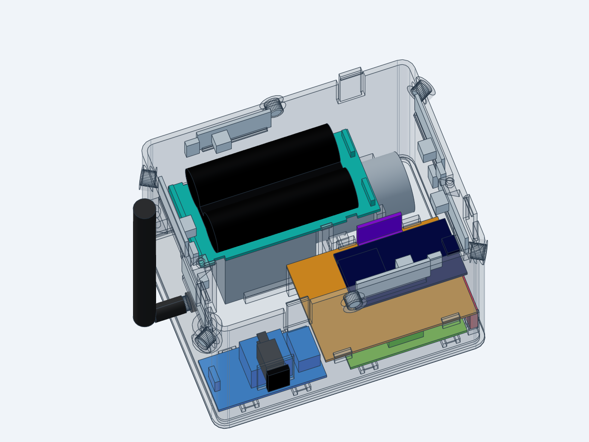
Inside the deck
Electronics inside the deck, deck walls
see-through
tan — perfboard: the board of holes the ESP32, the
IMU and the wiring are soldered on
dark navy — ESP32: the controller board that runs
the firmware
violet — IMU (GY-521, MPU-6050): the motion sensor
that measures how much the base is tilted
blue — relay module: a switch worked by the ESP32
that turns the pump on and off
green — buck module (XL4015): turns the battery’s
7.4 V into the 5 V the electronics use
red — BMS: battery protection board, cuts the power
if the cells run too low or too high or short out
charcoal — battery holder: two 18650 cells in
series
teal — battery tray
grey — pump
black — rocker switch: main power, in the −Y wall;
antenna: the WiFi antenna on the −X wall
orange — flame sensors, one in each sensor
collar
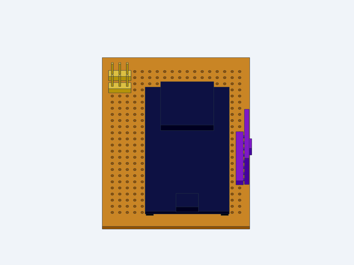
Perfboard
The perfboard with the ESP32 plugged
in
tan — perfboard
black — female headers: socket strips the ESP32
plugs into, so it can be pulled out
dark navy — ESP32
yellow — male headers: pin strips the two servo
cables plug onto
violet — IMU, standing on its right-angle header at the board
edge
Electrical terms
Header — a strip of pins (male) or sockets (female)
at 2.54 mm pitch.
Rail — a bare wire soldered along a column of holes
on the underside of the perfboard, shared by everything that needs that
supply: GND, 5V and 3V3 rails.
Solder bridge — a blob of solder joining two
neighbouring holes.
Jumper (J) — a short wire on the top of the
perfboard; wire (W) — any other wire. Each has an ID
that matches the cut list in the wiring guide.
Dupont jumper — a wire with a plug that fits on a
module’s header pin; the guide cuts them and solders the cut end to the
board.
GND, 5V, 3V3 — ground (0 V), the 5 V supply from
the buck, the 3.3 V supply from the ESP32.
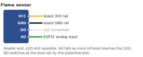
AO / DO — a flame sensor’s analog and digital
outputs; the turret reads AO.
COM / NO — a relay’s common and normally-open
terminals: they connect only while the relay is on.
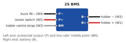
B+, B−, BM / P+, P− — the BMS’s battery pads
(cells’ plus, minus and middle) and its output pads.
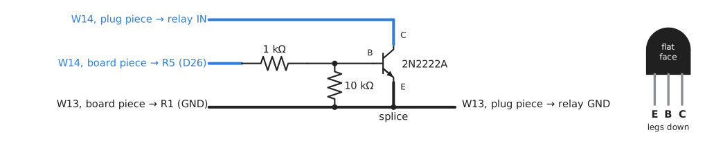
Transistor (2N2222A) — an electronic switch with
three legs: a small current into the base (B) lets a larger one flow
from the collector (C) to the emitter (E). The relay driver uses one to
pull the relay’s IN to GND.
Flyback diode — the 1N4007 across the pump; it
absorbs the voltage spike the motor makes when it switches off.
Heat-shrink — plastic tube slid over a soldered
joint and shrunk with heat to insulate it.
Pinouts
Each figure draws a module with its pins in their physical order and
the pin names printed on it. A connected pin carries a stub in its net’s
colour (the wiring guide’s colour code) and names where it goes: wire
IDs match the cut list, holes
use the labels printed on the perfboard. Grey pins stay unconnected.
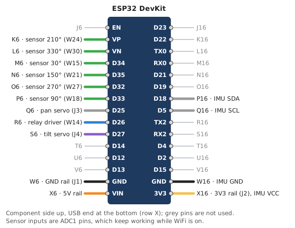
ESP32
The controller: it reads the six flame sensors and the IMU, aims the
two servos, switches the pump through the relay and serves the WiFi
control page. It runs on the 5V rail through VIN and its own regulator
supplies the 3V3 rail.
ESP32 DevKit pinout
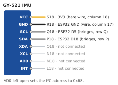
IMU
A motion sensor (accelerometer and gyroscope) that tells the ESP32
how far the base leans, so the aim stays level on uneven ground. It
talks to the ESP32 over I²C, two signal lines (clock and data).
GY-521 IMU pinout
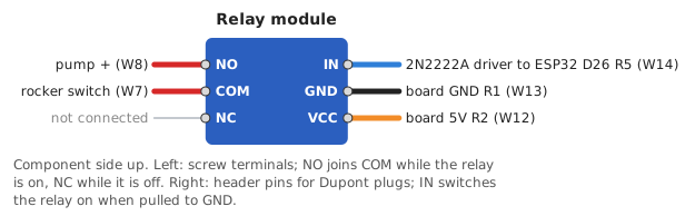
Relay module
An electrically worked switch: pulling IN to GND closes the contact
between COM and NO, which connects the battery to the pump. It keeps the
pump’s current away from the ESP32. The ESP32 drives IN through a
2N2222A transistor on W14 (the relay
driver), since its 3.3 V pin cannot hold IN at the module’s 5 V.
Relay module pinoutRelay driver: 2N2222A on W14 and
W13
Flame sensor
An infrared photodiode (the black LED) with a small amplifier. A
flame gives off infrared, so the closer or larger the fire in front of
the sensor, the lower its AO voltage; comparing the six sensors gives
the fire’s direction.
Flame sensor pinout
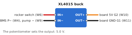
Buck module
A step-down converter: it turns the battery’s 6.0–8.4 V into a steady
5 V for the ESP32, the servos and the relay; the sensors run on the 3V3
rail from the ESP32.
XL4015 buck pinout
BMS
The battery protection board between the cells and everything else.
It cuts the output if either cell runs too low or too high, or if the
output shorts; BM lets it watch each cell on its own.
2S BMS pinout
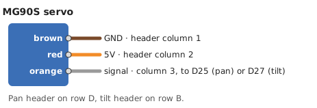
Servo
A motor with a gearbox and a position sensor that holds whatever
angle the signal wire commands (a pulse every 20 ms, its width sets the
angle). The pan servo turns the head, the tilt servo raises and lowers
the nozzle.
MG90S servo cable
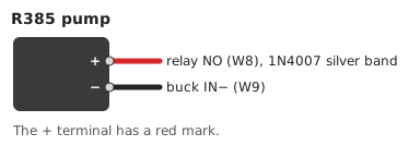
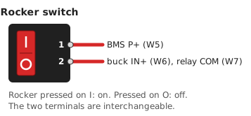
Pump and switch
R385 pump — a diaphragm pump driven by a DC motor;
it runs on the battery voltage while the relay is on. The 1N4007 across
its terminals absorbs the voltage spike the motor makes when it
stops.
R385 pump terminals
Rocker switch — the main power switch: it connects
the BMS output to the buck and the relay.